Understanding A Domestic Electricity Supply

In my previous post (“Assessing the accuracy of a consumer energy monitor“) I detailed the initial results of an investigation into the performance of the Owl+USB energy monitor.

As previewed in that post, I have subsequently installed another energy monitor – a special single phase version of the Crucible Technologies EML3Net – to gain more understanding of my electricity supply and consumption. With this monitor connected via RS485 to a Raspberry Pi, I am able to measure and record multiple parameters on an effective real-time basis (actually every minute but that is close enough to real-time for the purposes of this analysis!)

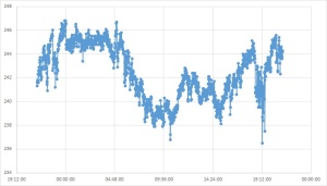
The following plot shows the supply voltage over a 24 hour period:

raw_volts

Plotting average voltage over half hour periods shows the trends more clearly:

hh_volts

Minimum measured voltage was 236V with a maximum of 247V and an average of 242V which is a very stable supply. Given that my electricity supply comes from a step down transformer located on a pole at the bottom of my garden, I would expect the supply voltage to be close to the top end of the UK statutory limit of 230V + 10% = 253V.

The new energy monitor allows me to measure both real, aka active, power and reactive power (and hence calculate apparent power). Wikipedia has a good article on AC power here but basically real power is what you pay for!

The following graph shows the power usage as measured by the electricity billing meter, the Owl+USB, the real power measured by the new electricity monitor and the calculated apparent power based on the real and reactive power measured by the new electricity monitor (Clicking on the graph zooms it):

powerplots


It is immediately clear that the Owl+USB is measuring apparent power not real power. On reflection this is unsurprising as it has no mains voltage reference input so can only assume a power factor of 1.

Looking at the actual power factor for my electricity supply over the same period confirms that an assumption of PF=1 isn’t valid for the majority of the time:

powerfactor

So while the Owl+USB does a reasonably good job of measuring relative electricity usage, it is of limited value in determining how much billable electricity is consumed – thus rendering the tariff feature of little use.

I had intended to use the Owl to ascertain if replacing an old fridge/freezer made economic sense. However I found that an inexpensive plug-in energy monitor (costing around £10) was actually a better solution for determining the energy consumption of individual appliances.

With the Meter Logger and LED Pulse Sensor installed and remotely accessible, my usage of the Owl is now minimal.
Assessing the accuracy of a consumer energy monitor

There are a large number of after market add-on electricity energy monitors in the market. In this blog, I assess the performance of one of the more common devices; the Owl+USB.

The Owl+USB is targeted primarily at the consumer market and retails for around £40-50 inc VAT. It is simple to install and provides:

  • a real time display of electricity usage
  • display of historical usage data (by year, month, day or hour) on a PC
  • data download to a PC connected via USB

It is interesting to note that neither the Owl website nor the manual provided with the product make any statements about accuracy.

I have had a Owl+USB installed at home for the last couple of years. Initially I spent a reasonable amount of time analysing my electricity usage (no, its not worth the hassle to turn the PVR and surround sound system off rather than leave them on standby) and establishing how much power individual items consume (tumble driers are really bad!). With low energy bulbs installed throughout my house, I can’t really detect when someone has left a light on but it is obvious when the electric oven or a fan heater is on.

However I have been concerned that the energy usage reported by the Owl didn’t agree with my meter. To try and understand the discrepancy, I have installed a Crucible Technologies Meter Logger 100 and LED Pulse Sensor. This monitors the electricity usage as recorded by the meter using the flashing LED indicator in the meter.

The following table gives the electricity usage as measured by the revenue meter, the Owl+USB and the Meter Logger for the period 4:00pm on July 31 to 8:00am on Aug 7:

Source kWH
Revenue Meter 76
Owl+USB 90.3
Meter Logger 75.9

So the Owl+USB is measuring high by about 18%. There is a settable voltage parameter on the Owl which is currently set to 240V. I have monitored the supply voltage to my house and it typically ranges between 230V and 245V. It would need to be as low as 200V to explain the over measurement which is not realistic.

Looking at the performance of the Owl in more detail:

1. Total Daily Electricity Usage

DailyElectricity

Clearly the Owl is reading consistently high.

2. Half Hourly Electricity Usage Over A Day

Looking at the error in the Owl measurement per half hour period over a day:

IntraDay

The Owl does a pretty good job of tracking the relative energy consumption and most of the data shows the Owl reading high. However there are isolated examples (e.g. half hour period ending 13:00) when the Owl reads slightly low.

According to the Owl website, the current clamp supplied with the Owl is rated up to 71 Amps. This type of current clamp is typically specified down to a minimum current of between 5% and 10% of the rated current i.e. 3.55 Amps to 7.1 Amps. At 240V, a steady current of 3.55 Amps equates to a energy usage of 850 WHr – which is greater than the typical energy usage of my house. Even the peak demand of around 2 kWHr (=2000 WHr) equates to a current of only just over 10% of the rated current of the clamp. So the error in the Owl measurement may simply be an indication that the supplied current clamp is over rated for typical domestic energy consumption.

As a next step, I plan to install a different add-on energy meter and evaluate its performance…

Interference from 4G Mobiles

The possibility of certain 4G mobile transmissions interfering with television signals has been widely acknowledged and publicised – see for example the DailyMail from June of last year with its carefully considered article “Millions of households could lose television signal as 4G network is switched on” or for a more reasoned approach read TechRadar from Nov 2013 “4G could ruin your TV: here’s what will save it

However the likelihood of interference with short range devices has been largely ignored or downplayed. Short range devices, or SRDs, have many applications including wireless smoke alarms, fire alarms, intruder alarms, social alarms (panic buttons for elderly or disabled), smart meters, home automation devices and RFID tags. SRDs have been on the market since 2004 and the industry estimates are that there are over 94 million wireless smoke alarms and over 80 million wireless security devices installed across Europe.

SRDs operate in the 863MHz to 870MHz radio spectrum bands. 4G mobiles operate in a number of frequency bands including one at 800MHz. Out of band emissions from a 4G mobile using the 800MHz frequency have the potential to interfere with SRDs.

Internal tests at Tele-Products have proved the potential for life threatening interference. A social alarm had a range of 30m in the absence of 4G interference. Introducing simulated interference from a 4G handset operating at a distance of 6m from the alarm receiver, reduced the effective range of the alarm to only 10m.

The SRD industry has long recognised the possibility for interference – see letter from Euralarm trade body published here –  and recently, albeit belatedly, the European Commission has acknowledged it – see the letter here. However their proposed “solutions” are unrealistic and do not address the issue of 4G mobiles and SRDs already deployed or on sale.

While not providing a solution, the 4G-OOBS product available to rent or buy from Crucible Technologies here will at least allow manufacturers and users of SRDs to assess the impact of 4G interference.

4GOOBS med res

Detecting and Understanding Power Outages

Returning to work after the 4 day Easter break, it was immediately apparent that there had been an interruption to our business electricity supply; the security and fire alarm systems were both registering a power cut.

Over the prior week we had noticed that the voltages on our incoming 3-phase supply although still within specification were low – around 228V to 230V – and on the Blue phase was running as low as 223V. We assumed that this was as a result of local major civil engineering and construction works (building a new Park-and-Ride terminal for York).

We monitor our electricity usage in two ways; firstly using a LED pulse sensor attached to our revenue meter and connected to a Meter Logger 100 and secondly using an EML3Net connected with both current transformers and voltage taps.

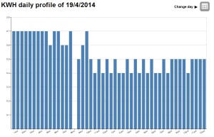
Reviewing the logged electricity usage, it was clear that the power cut had taken place early on Saturday morning. The usage graphs below are from the LED pulse sensor & Meter Logger 100 and show a normal Saturday (12 April) and this last Saturday (19 April):

NormalSaturdayPowerCut Annotated

From the top graph, our normal background consumption level is between 600Wh and 700Wh generated by our Servers and Desktop PCs left on to allow users to log in remotely.

From the lower graph:

  1. From midnight until 07:30, electricity consumption is running at normal background level (labelled “pre outage” on the graph)
  2. There is anomalous low consumption between 07:30 and 08:00 which is when the power cut occurred (indicated with the red oval on the graph). However the electricity supply was apparently absent for only part of this half hour period as some usage is recorded.
  3. After the electricity supply has been resumed, the background consumption level has reduced to between 400Wh and 500Wh. This is due to Desktop PC’s not automatically restarting after the power was restored.

Note: Our Servers are protected by a UPS so did not turn off or re-boot.

While this data is informative and allowed us to identify when the power cut took place, the data from our EML3Net is even more interesting.

The EML3Net contains a mains powered sub-meter and the ring main to which it is connected is powered from the Blue phase of our 3-phase supply. The graph below shows the electricity usage recorded by the ELM3Net:

PowerCut

Note: The EML3Net logs electricity usage with a resolution of 100Wh (0.1kWh) whereas the pulsed LED on the revenue meter flashes every 1Wh

As can be seen, the EML3Net recorded NO electricity usage between 07:30 and 08:00. From internal tests, we know that the unit takes less than 30secs to boot up and start logging once power is applied. So our working assumption is that the Blue phase (from which the mains power for the unit is derived) took longer to come back live than at least one of the other phases.

Checking the voltage levels on the incoming 3-phase supply this week, all phases are now consistently operating at between 240V and 245V. It may be reasonable to assume that there have been changes to the area electricity supply made over the weekend with possibly an unplanned power interruption but ultimately providing an improved quality of supply.


PAT Training Options

First Stop Safety launches a new White Paper today hoping to dispel some of the myths surrounding PAT training options.

C&G versus alternative PAT training options‘ is a free to download White Paper aiming to help delegates better understand the PAT testing qualification available through both the City & Guilds organisation and other PAT training providers.

This is helpful information for anyone considering Portable Appliance Testing (PAT) training. There are many options to choose from, and this White Paper will help delegates choose the best training course for them or their employer.


Accurate Remote Energy Monitoring

Traditional retro-fit or add-on remote energy monitoring systems use current transformers to monitor the current flowing in supply cables. These systems are often very easy to install (see photograph below) and are useful for detecting excursions in energy consumption or qualitatively checking that energy saving measures are having an effect.

CTs in place

However the accuracy of these systems is limited by a number of factors:

  1. The current transformers inherently have a finite accuracy typically +/- 1%
  2. The majority of these systems assume a fixed supply voltage. However the mains voltage in the UK can vary by up to 10%
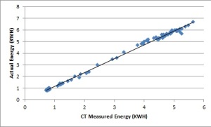
  3. For 3-phase supplies, unless the voltage and power factor of all 3 supply phases is measured, the systems do not measure real power – as changes in power factors and supply voltages are ignored. This alone can result in a 20% – 30% discrepancy between the energy consumption as recorded by the revenue meter and by the remote energy monitoring system. The graph below shows an example of the difference between CT measured and actual energy consumption – actual being the amount recorded by the billing meter.

CT vs Actual Energy

Some modern energy meters are equipped with an electrical pulse output, in which case these can connect directly to a pulse data logger – such as the Crucible Technologies Meter Logger 100However the majority of energy meters installed in domestic and commercial premises do not yet have the pulse output feature.

To date, the usual solution for accurate remote energy monitoring has been either  to replace the existing energy meter with a pulse output equipped meter or to install a secondary meter – for example the Crucible Technologies EML3Net – with both current and voltage measurement. Both of these solutions require an interruption of supply and need to be fitted by a qualified electrician.

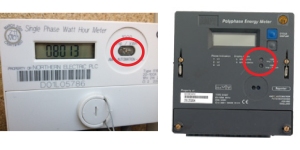
The LED Pulse Sensor from Crucible Technologies coupled with the Meter Logger 100 provides a solution which can be applied to any meter with a pulsed LED output – a little red light which flashes at a rate proportional to the amount of energy being supplied by the meter. Examples of a domestic single phase and commercial 3-phase meter fitted with pulsed LED output are shown below – with the pulsed LED circled in red. Adjacent to the pulsed LED is typically an indication of the pulse frequency e.g “1000 imp/kWH” meaning each flash indicates 1 WH used.

Pulsed LED Meters

The LED pulse sensor is very easy to attach to the meter and alignment guides ensure that the sensor is correctly placed. Once fitted to the meter (see photo below), it is connected to an input on the Meter Logger 100 using inexpensive two core cable; for example loudspeaker cable. Up to 20m cable can be used which allows the Meter Logger 100 to be conveniently located.

Light Sensor TP Meter low res

The Meter Logger 100 will now record exactly the same energy consumption as the meter but with the benefit of being able to view energy consumption over the web, download into spreadsheet/database programs or send the data via e-mail to AM&T software e.g. Enmat

New Product: MemoryPAT-Blu

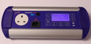
First Stop Safety today launched the new Portable Appliance Tester ‘MemoryPAT-Blu’.

MemoryPAT-Blu

Manufactured in the UK by First Stop Safety, this new tester is an exciting addition to the already highly successful ‘BattPAT’ and ‘MemoryPAT’ because users will benefit from the built in Bluetooth connectivity. 

The MemoryPAT-Blu retains everything that makes the MemoryPAT tester so popular with electricians and PAT testers. The Bluetooth technology takes the tester one step further by enabling users to easily and wirelessly transfer test results and data using the free First Stop Safety Android App  ‘PATRec‘.

The MemoryPAT-Blu is very easy to use and benefits from the manufacturer’s Lifetime Warranty. This Warranty is extended free of charge at every First Stop Safety annual calibration.

For more information click here.

New Product: Earth Leakage and Load Current Meter

ELT mediumFirst Stop Safety today launched the Earth Leakage and Load Current Meter (“ELT”). Targeted primarily at anyone involved in the repair and maintenance of electrical equipment, the ELT provides a continuous measurement of the earth leakage and load currents for any Class I or Class II mains powered equipment under normal operating conditions.

The measurement of Load Current is useful as a higher than normal current draw can indicate a faulty appliance. This measurement is advisable specially after an appliance has been repaired. The rating plate of the appliance should indicate the maximum power consumption, from which the maximum current can be easily calculated.

The ELT is very simple to use and benefits from a Lifetime Warranty – providing it is calibrated annually by First Stop Safety

For more information, Click Here

Split Core Current Clamps available from Crucible Technologies

Available now from Crucible Technologies, the Mini Hinged Current Clamp (MHCC) and the  Split Core Current Clamp (SCCC) provide a safe and easy way to monitor energy usage. Both can be easily connected over existing mains power cables without disconnection or interruption of supply.

The MHCC is designed for use with supply currents up to 80Amp and can accommodate cable diameters upto 10mm. For larger cable diameters up to 17mm and higher currents of 150Amp, the SCCC can be employed.

Both the MHCC and SCCC have an internal shunt so that the maximum output voltage is only 0.333V. Seggy Segaran, Technical Director of Tele-Products said “The low output voltage of these devices makes them a much better option than some other current transformers which can produce dangerously high voltages”.

Click Here for more information.

Wireless Connectivity for Meter Logger

Extending the possible applications and compatible locations for the Meter Logger, Tele-Products have developed a solution which allows the unit to connect to a wireless network.

The Meter Logger is equipped with a standard ethernet socket and easily connects into an existing wired network but feedback from customers indicates that in a significant percentage of locations, the network cabling may not extend into distribution or utility meter rooms. However many businesses have wireless networks with coverage over the whole site.

Connecting the Meter Logger to a Wireless Router or Access Point, configured in “Client Mode” and itself connected to the wireless network, allows the Logger to appear on the business’s network and thus make the utility consumption data available to any computer.
(Note: In Tele-Products testing, both a TP-Link Wireless N Nano Router and a D-Link DAP-1160 were used but there is no reason to believe that other routers which provide “client mode” operation could not be successfully configured)

Click Here for more information about the Meter Logger